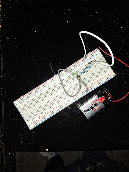
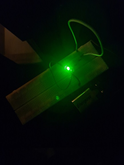
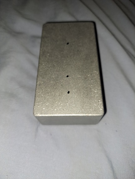
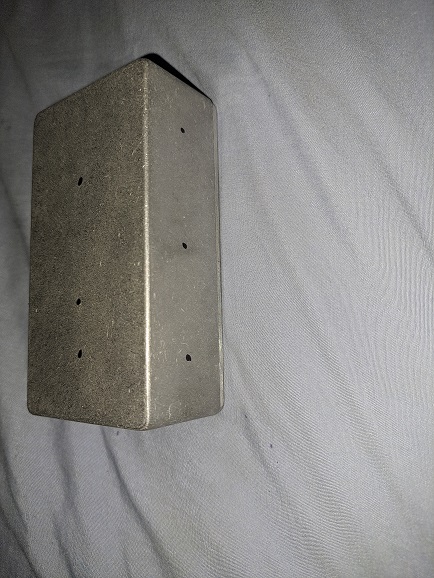
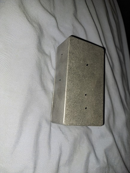
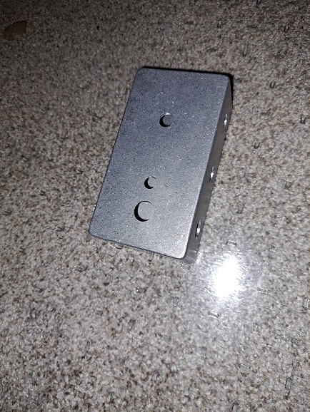
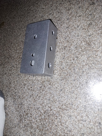
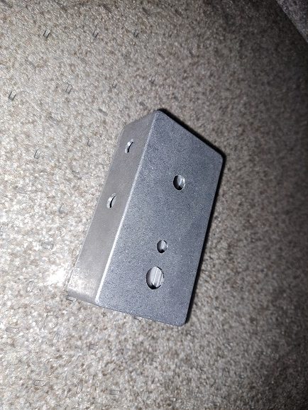
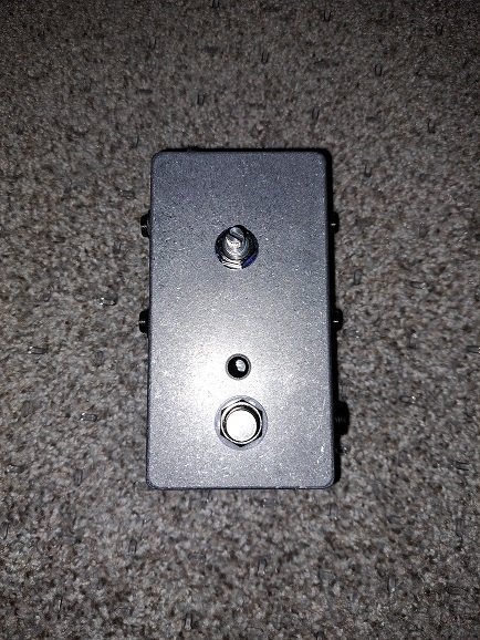
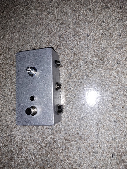
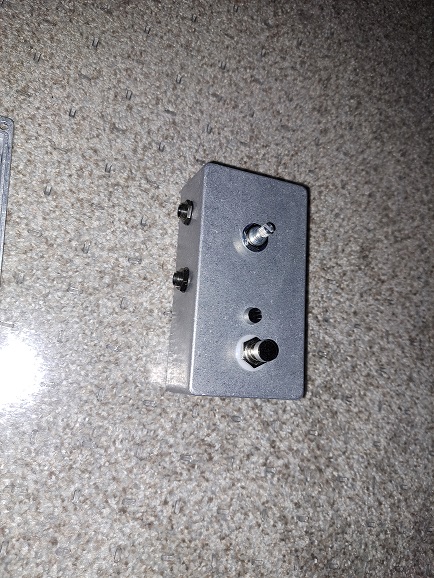
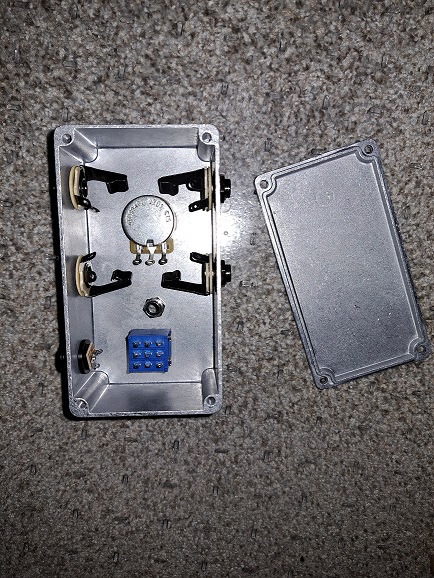
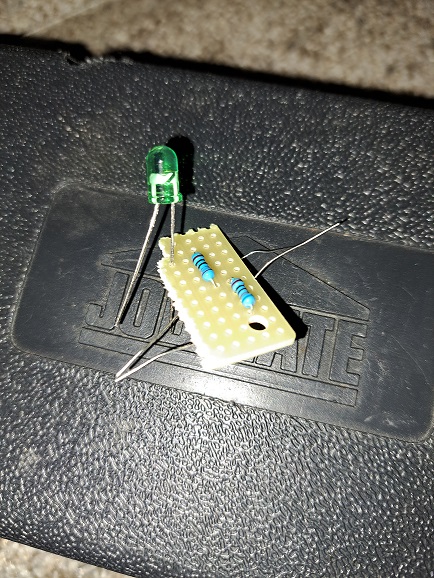
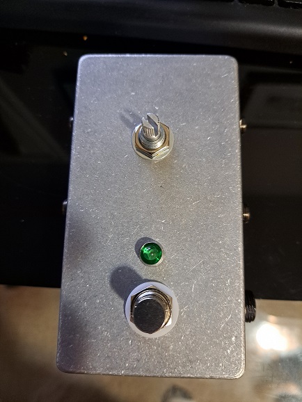
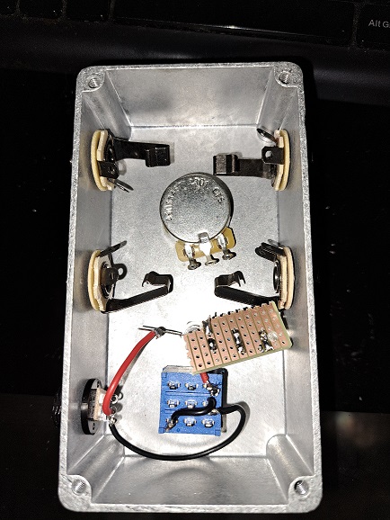
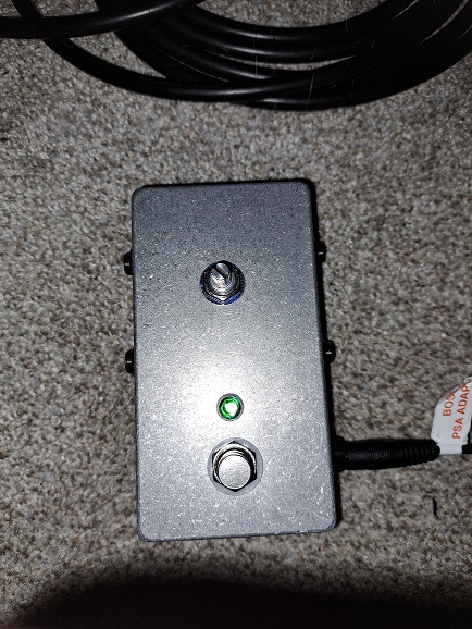
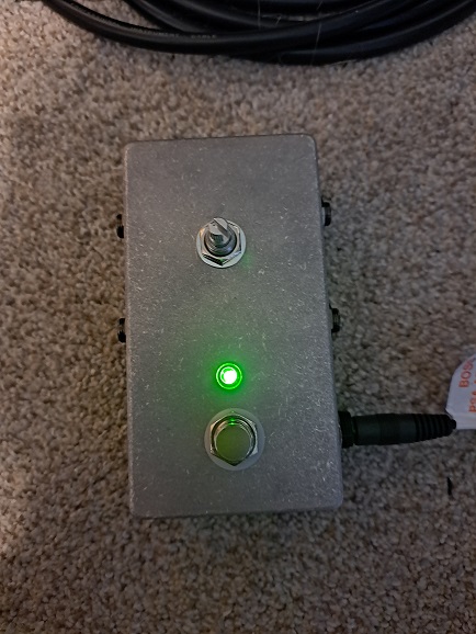
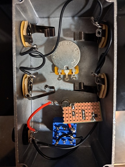
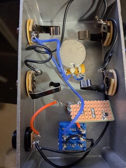
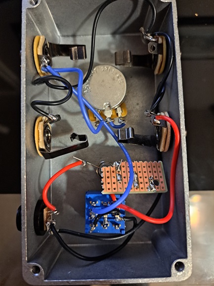
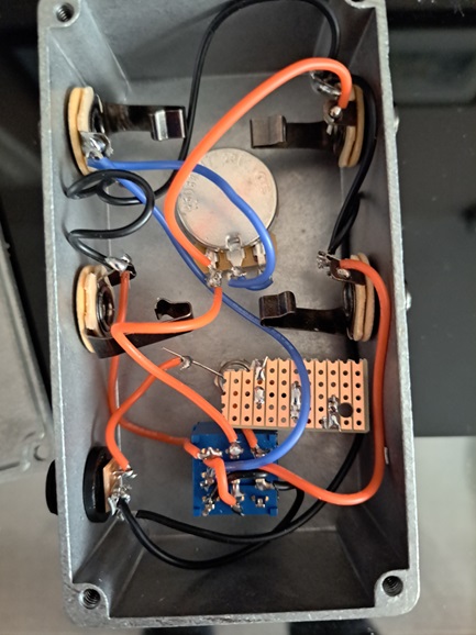
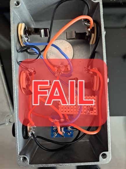
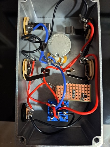
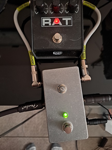
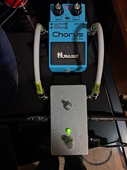
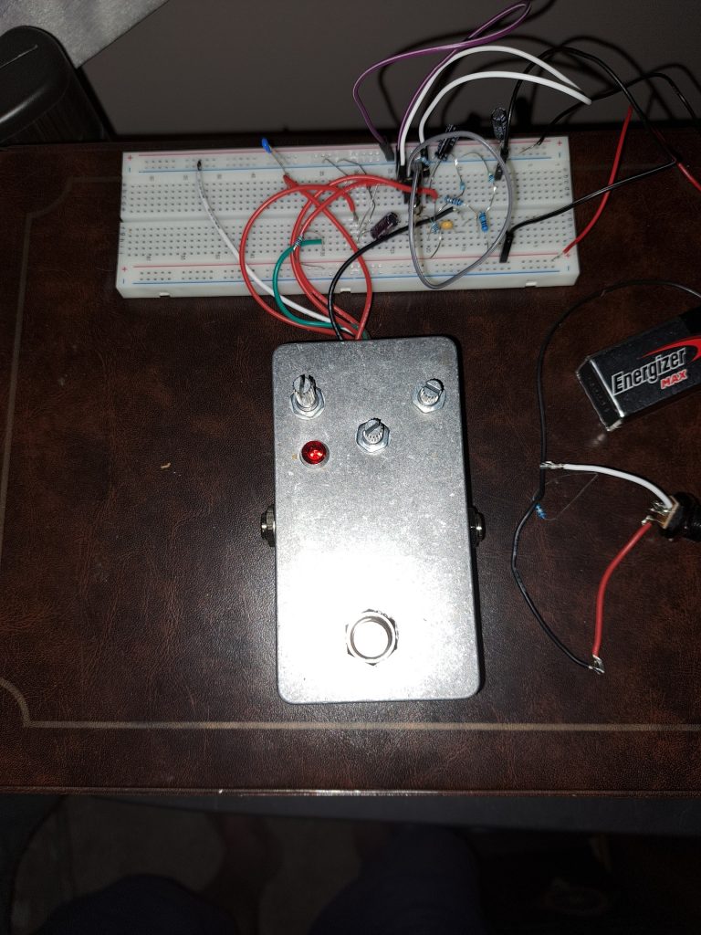
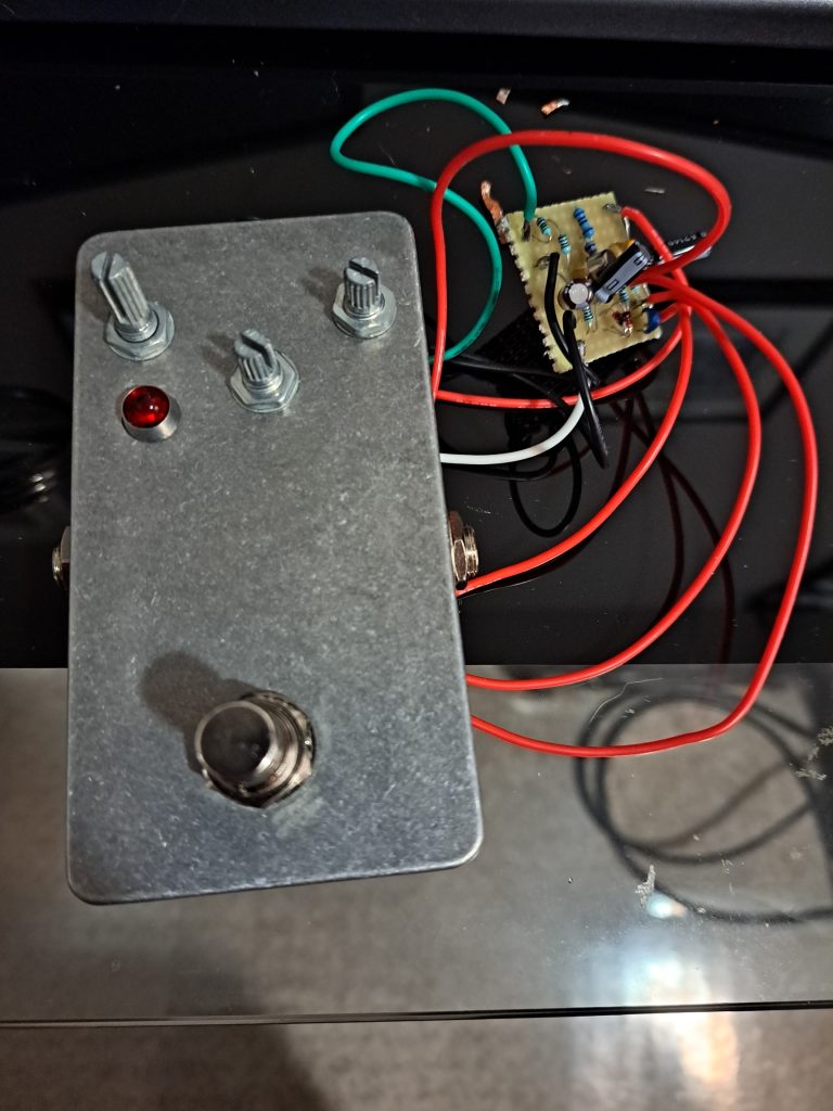
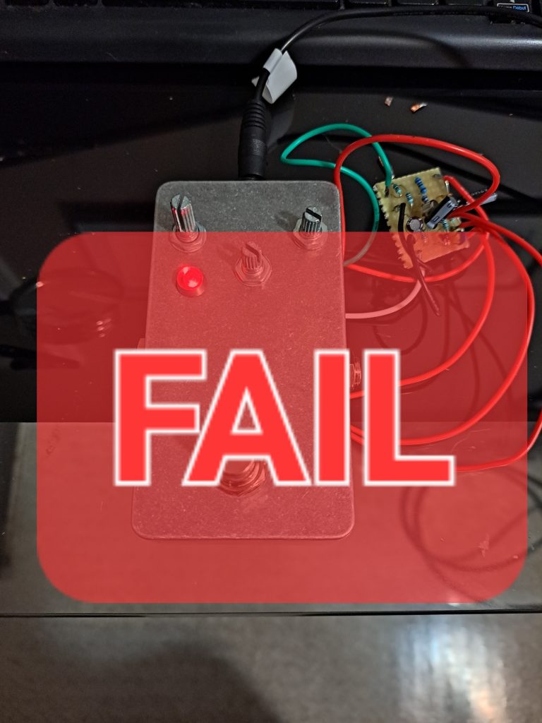
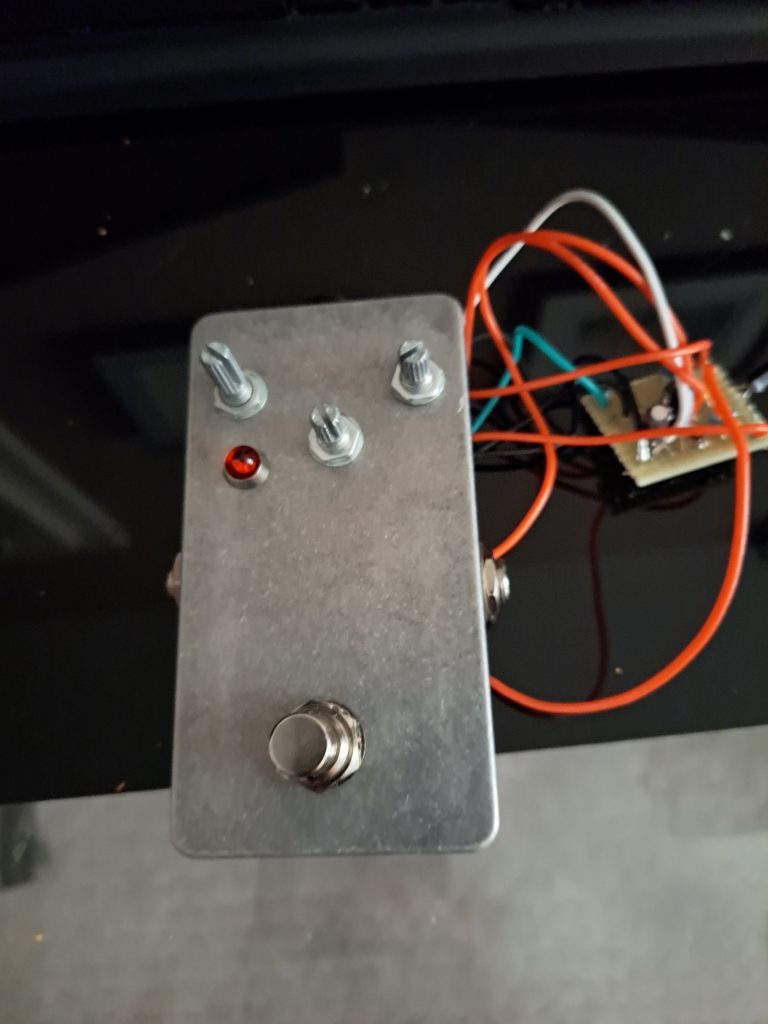
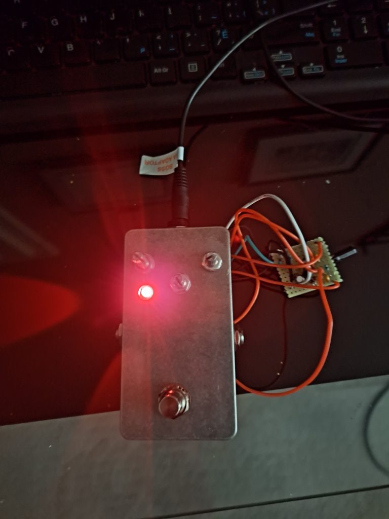
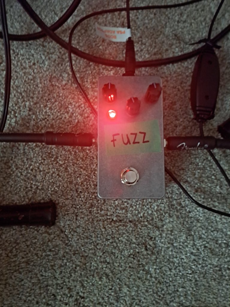
Guitar Pedal Workshop


Feedback Looper pedal Project #2


LED Test circuit breadboard
Green LED test board
125B Top Enclosure
125B Enclosure Top marked for drilling holes
125B Right Enclosure
Right side of Enclosure
125B Left Enclosure
Left side of Enclosure
Holes Drilled on Top
Holes Drilled on the Right
Holes Drilled on the Left
Dry Fit Components Top
Dry Fit Components Right
Dry Fit Components Left
Dry Fit Components inside
LED Circuit Board
LED Circuit Board
LED Added
LED Added
Tiny Curcuit Board inside
Add a power supply to the pedal
LED works
LED works!!!
Ground Wire Added
Black Ground Wire Added
Soldered blue wire for the components
Some more Wiring added
All wires are soldered
All wires are soldered. Ready to be tested next.
Failed wiring
The wiring for the potentiometer was incorrect. Had to reverse the wires
Here is the correct wiring for the potentiometer. Now we can do some demos.
Feedback Looper + Rat2
Feedback Looper + Chorus


Distortion/Fuzz pedal Project #1


Distortion/Fuzz pedal project 1
Fuzz/Distortion test pedal Demo
Guitar Pedal fail
Fuzz pedal complete
Are you 21 or older? This website requires you to be 21 years of age or older. Please verify your age to view the content, or click "Exit" to leave.